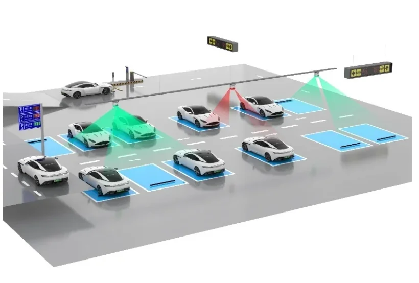
A parking guidance system site survey checklist helps integrators define a project beyond a device list. However, the same sensors, signs and software can behave very differently when the parking layout, driver decision points, network boundaries and operating rules change.
A useful survey turns those conditions into testable project inputs. It does not replace detailed engineering or lock the project to performance guesses without evidence. Instead, it shows what teams must know before they can trust the system design, quotation and acceptance plan.
Therefore, use the following checklist to give the survey a clear and practical structure.
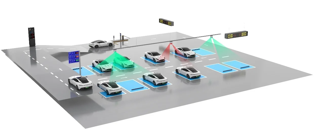
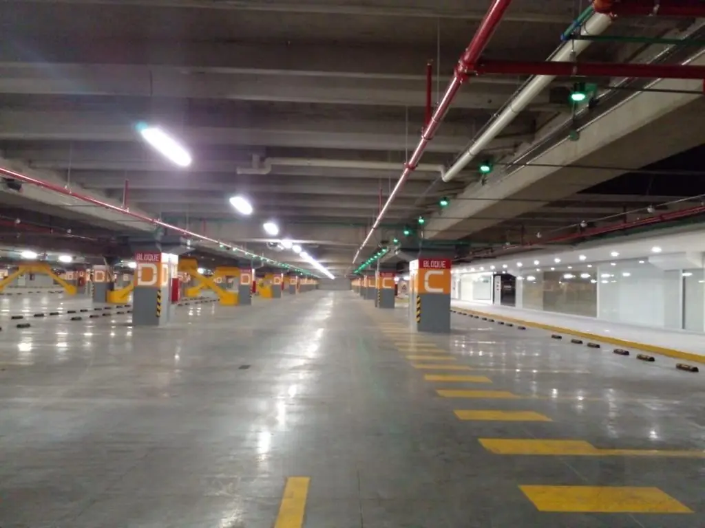
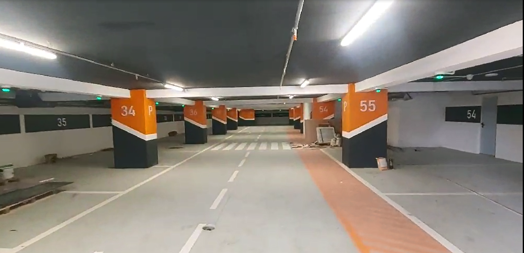
Illustrative system overview: use the site survey to connect each driver decision point with sensing, display and operating requirements.
1. Start with the operating objective
First, write down what the project should improve before discussing equipment.
For example, the project may need to:
- show drivers whether spaces are available before they enter a level;
- route vehicles toward zones with usable capacity;
- distinguish public, reserved, accessible or other controlled space types;
- give operators a current view of occupancy and device status;
- support a defined manual process when sensing, signs or communications are unavailable.
These goals differ. As a result, each one changes what teams must sense, display, connect and test. Finally, record who owns each goal and how the project team will confirm the result.
2. Map the driver journey and every decision point
Next, walk the route as a first-time driver would. Begin before the site entrance and continue through ramps, intersections, level changes, search aisles and exits.
At each point, record:
- what the driver must decide;
- what information is needed to make that decision;
- how early the information must be visible;
- whether the driver can safely change direction;
- what happens when the intended zone is already full;
- whether a temporary closure or reserved area changes the message.
For example, an entrance display, a zone display and an aisle indicator do not serve the same decision. Avoid placing a sign simply because power or mounting is convenient. Instead, place it where it supports the driver’s decision.

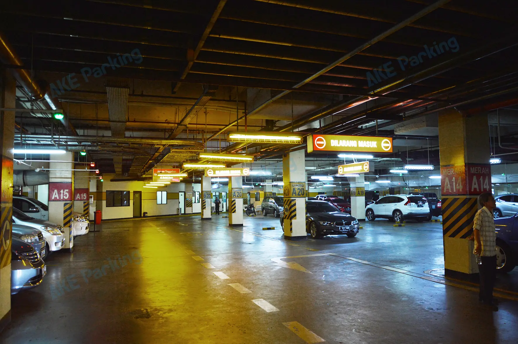
Edited illustrative view: place a guidance display around a real driving decision, not only where installation is convenient. We do not present this image as a customer project record.
3. Confirm the parking inventory and counting boundaries
Then, obtain the current plan and verify it on site. Draw boundaries that match how operators will use the facility.
Record:
- total spaces by level and zone;
- individually controlled or specially designated spaces;
- spaces that are temporarily removed from normal inventory;
- areas shared with loading, valet, charging or other operations;
- ramps, circulation areas and non-parking zones that must not be counted;
- the rule for moving a space between available, occupied, reserved, blocked or unknown states.
Do not assume the architectural count is the live operating count. Therefore, agree on a controlled inventory list and name the person who will approve changes after handover.
4. Survey the sensing environment
In addition, document conditions that may affect installation, detection, maintenance or communications without inventing a product-specific limit.
For every proposed sensing area, capture:
- ceiling or mounting structure and available height;
- space geometry and aisle orientation;
- columns, beams, ducts, cable trays and other obstructions;
- lighting conditions and reflective surfaces;
- dust, moisture, temperature exposure and cleaning practices;
- nearby equipment that may create interference or access constraints;
- safe maintenance access and isolation requirements;
- cable routes, junction points and containment responsibility.
If a condition needs a specific coverage distance, accuracy, environmental rating or installation tolerance, mark it for model-level engineering review. Therefore, do not turn a generic site survey into a product promise without evidence.
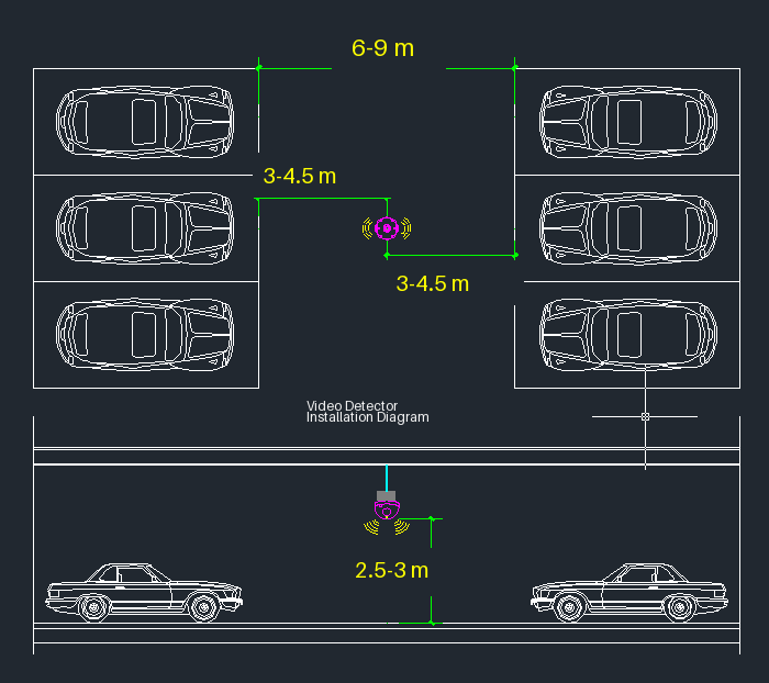
Example single-gantry layout only. Final spacing, coverage and mounting height depend on the selected model and surveyed site conditions.
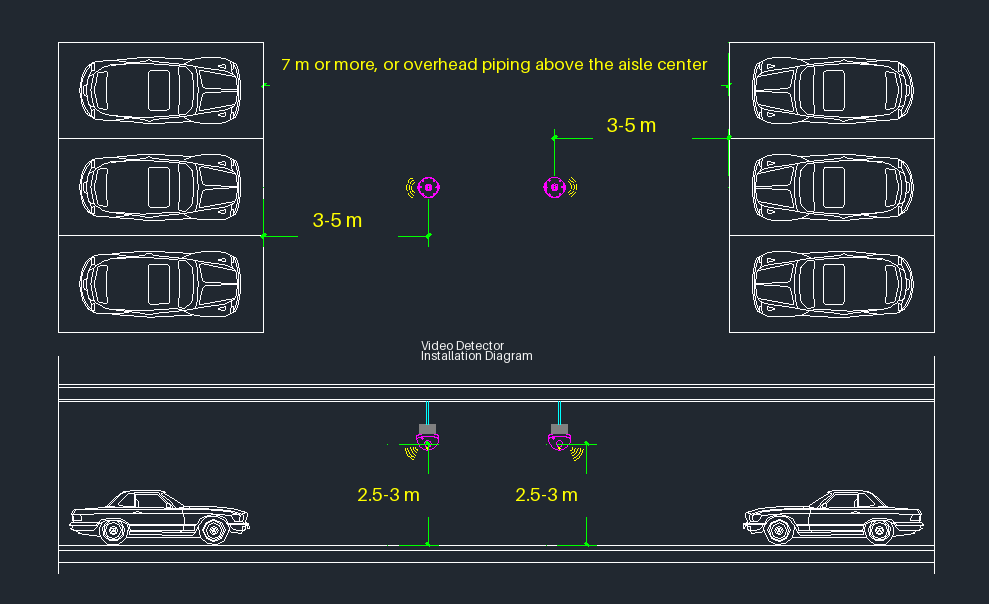
Example dual-gantry layout only. Final spacing, coverage and mounting height depend on the selected model and surveyed site conditions.
5. Define the sign and display hierarchy
Next, create an information hierarchy before choosing display sizes or quantities.
A common hierarchy may include:
- site or facility availability before entry;
- level or major-zone availability;
- direction at each branching point;
- local aisle or space indication where the operating model requires it.
For each display location, record:
- intended message and source of that message;
- viewing direction, distance and possible obstruction;
- ambient light and glare conditions;
- required language, symbols and number format;
- mounting, power, network and maintenance access;
- behavior when data is stale, unavailable or contradictory.
However, public-road sign rules do not automatically govern internal garage wayfinding. The project team should identify the applicable local code, owner standard and authority having jurisdiction instead of copying a road-sign assumption into the garage.
6. Draw the power, network and data boundaries
Similarly, a single line on a schematic is not enough. The survey must make responsibility visible.
Create a boundary diagram that identifies:
- device power source and isolation points;
- network segments, cabinets, switches and upstream ownership;
- permitted protocols and security zones;
- time synchronization source;
- server, controller or cloud responsibility;
- data fields exchanged with parking, access, payment, building or third-party systems;
- logging, retention and diagnostic access;
- who investigates a fault on each side of an interface.
For consistency, use clearly defined terms when systems exchange parking data across facilities, zones, spaces, occupancy states and events. The Alliance for Parking Data Standards provides a common data language that can help teams align those terms. However, this reference does not prove that any particular AKE product implements a given standard or version. Teams must verify product compatibility separately.
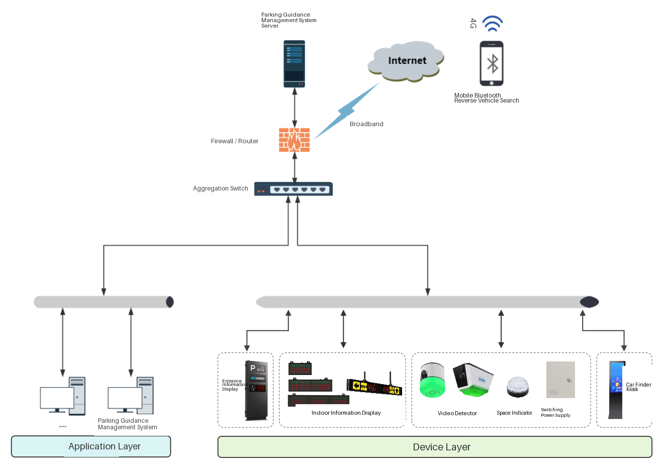
In practice, a boundary diagram should show which application, network and field-device components sit inside the project scope and who owns each interface.
7. Design degraded and manual operation
However, every site will eventually experience a failed sensor, disconnected network segment, unavailable sign or inconsistent count. Agree on the safe operating response before commissioning.
Therefore, the survey should answer:
- What will a sign display when its source data is unavailable?
- Can operators mark a space or zone unavailable manually?
- How is a stale count identified and corrected?
- Which functions continue locally during an upstream outage?
- How are faults acknowledged, escalated and closed?
- What evidence is retained for troubleshooting?
- Who may apply a manual override, and how is it removed?
The goal is not to promise uninterrupted operation. It is to define observable states, responsible people and a controlled fallback.
8. Turn the survey into acceptance tests
Write the acceptance plan from the surveyed decision points and failure modes. Do not add it after installation.
For each test, record the precondition, action, expected visible result, expected system record, responsible witness and retest rule. Include at least:
- normal arrival, occupancy and departure in each representative zone;
- changes that affect entrance, level and directional counts;
- specially designated or reserved-space behavior;
- sensor or device fault indication;
- network interruption and restoration;
- stale or unavailable display data;
- manual override and return to automatic operation;
- inventory correction and audit trail;
- operator login, role and handover checks where applicable.
In addition, include photographs, marked-up drawings, configuration exports, device lists and signed test results in the handover evidence. Define the required format and owner before testing begins.
9. Complete the parking guidance system site survey checklist before requesting a quotation
Before you request a quotation, use this short list to check whether the project is ready for engineering review:
- [ ] Current site plan, levels, zones and controlled parking inventory
- [ ] Driver routes and every information decision point
- [ ] Space types requiring separate rules or counts
- [ ] Mounting conditions, obstructions and maintenance access
- [ ] Proposed display locations and viewing conditions
- [ ] Power, containment and network responsibility
- [ ] Required interfaces and data ownership
- [ ] Degraded operation and manual override process
- [ ] Applicable local codes and owner standards
- [ ] Acceptance scenarios, witnesses and handover evidence
If several items remain unknown, keep them visible as project assumptions. Otherwise, hidden assumptions will make the quotation difficult to compare and harder to commission.
10. Use product pages after the requirements are defined
Finally, review the parking guidance system site survey checklist, confirm the survey boundaries, and map the requirements to the relevant product family. Then request model-level confirmation.
AKE’s public pages that may help with that next step include:
- parking guidance system product category;
- ultrasonic parking guidance sensor;
- entrance parking guidance display;
- LED indoor parking guidance display;
- AKE smart parking solutions showroom overview.
However, these links provide context, not a project design or compatibility guarantee. Final model selection, installation limits, interfaces and performance claims require current product evidence and an accountable technical review.